Inside the CDNA5 Tensor Data Mover
Most of a matrix-multiply kernel isn’t multiplication. Before the hardware can multiply anything, someone has to fetch the numbers: compute an address for every thread, issue a load, wait for it to come back, copy it into fast local memory, wait at a barrier so everyone agrees it’s there. Only then does the math happen. Count the instructions in a real GEMM kernel sometime. The arithmetic is a small fraction of them.
CDNA5 moves that fetching into dedicated hardware called the Tensor Data Mover. You describe a chunk of memory you want, hand the description to the engine, and it goes and gets it while your kernel keeps running.
Some vocabulary first, since the rest of this leans on it:
| Term | What it means |
|---|---|
| Wave | A group of 32 threads that execute together in lockstep. The unit of work on the GPU. |
| VGPR | A vector register. Each of the 32 threads gets its own copy. These are scarce. |
| SGPR | A scalar register. One copy shared by the whole wave. Much cheaper than a VGPR. |
| LDS | Local Data Share, a small fast scratchpad that all threads in a workgroup can read. |
| WGP | Workgroup Processor, the hardware block holding 4 SIMDs and one LDS. |
| Tile | The rectangular chunk of a big matrix that a kernel works on at a time. |
TL;DR. The Tensor Data Mover is a DMA engine that copies a tile of an array from global memory into LDS. You set up a descriptor in about a dozen SGPRs, issue one instruction, and it does the whole copy on its own while your wave gets on with other work. It handles arrays of up to 5 dimensions, clamps reads and writes that run off the edge, can insert padding to avoid LDS bank conflicts, and can broadcast one tile to as many as 16 workgroups at once. A counter called TENSORcnt tells you when it has finished. The point of all of it: the copy for the next tile happens while the matrix core is still working on this one.
Everything below is checked on hardware. The descriptions come from AMD’s published CDNA5 ISA manual, and I then built descriptors by hand and ran them on an MI450 (gfx1250, ROCm 10.1) to see whether the hardware agrees. Padding, gather, the bounds handling and the addressing all behaved as documented. This is my own testing on one machine, not endorsed or reviewed by AMD.
Why bother with a DMA engine
There are three ways to get data from global memory into LDS on CDNA5, and they’re worth seeing side by side.
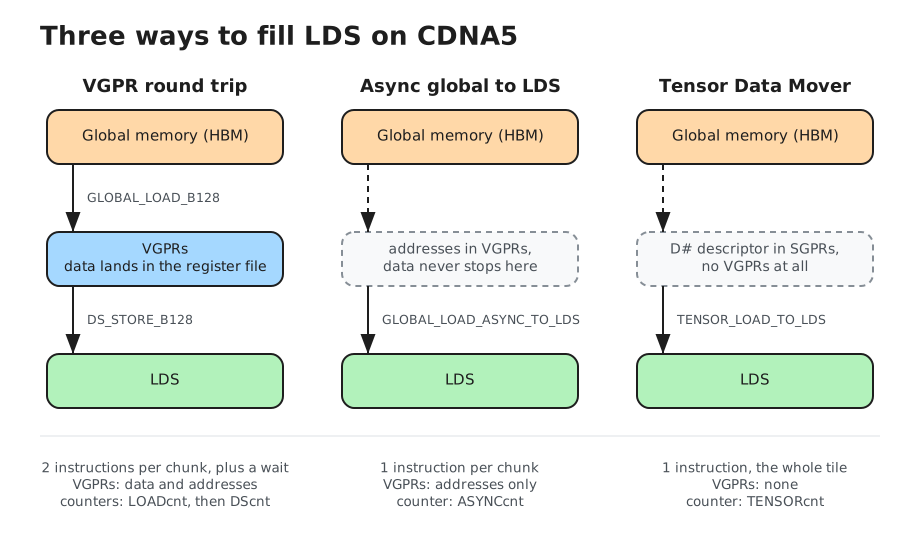
The old way is a round trip through registers: load from memory into VGPRs, wait, then store from VGPRs into LDS. It works, but the data takes a detour through the register file, and those are the registers your accumulator wants.
The async loads added in recent generations skip the register file, sending data straight from memory into LDS. Better, but every thread still computes its own address, so one instruction only moves 32 lanes’ worth of data.
The Tensor Data Mover does neither. From the manual:
Tensor instructions are encoded as VIMAGE or VGLOBAL instructions but use no VGPRs and are not performed per-lane.
No VGPRs at all, and nothing computed per thread. One instruction moves the entire tile, however big you said it was. Think of it less as a load and more as handing a work order to a helper that runs alongside you.
| Register round trip | Async to LDS | Tensor Data Mover | |
|---|---|---|---|
| Instructions per tile | 2 per chunk, plus waits | 1 per chunk | 1 total |
| VGPRs used | data and addresses | addresses only | none |
| Who computes addresses | every thread | every thread | the engine |
| Multi-dimensional | you write the loop | you write the loop | up to 5D in hardware |
If you know NVIDIA’s Tensor Memory Accelerator on Hopper, this is the same idea with different details.
Where it sits
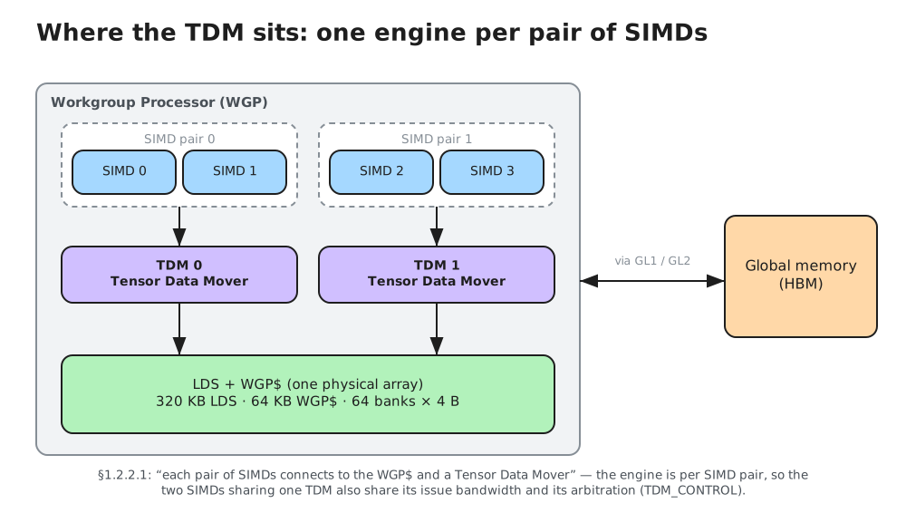
There’s one engine for every pair of SIMDs, so two per Workgroup Processor. They write into the LDS, which on CDNA5 is 320 KB split into 64 banks of 4 bytes each. Hold on to that bank number, it explains a feature further down.
Driving it
Two instructions, one in each direction:
TENSOR_LOAD_TO_LDS      ; global memory -> LDS
TENSOR_STORE_FROM_LDS   ; LDS -> global memory
Neither takes the data as an operand. Instead they point at a descriptor, called the D#, which is just a block of SGPRs you fill in beforehand. A 2D copy needs 12 of them, the full 5D version needs 20.
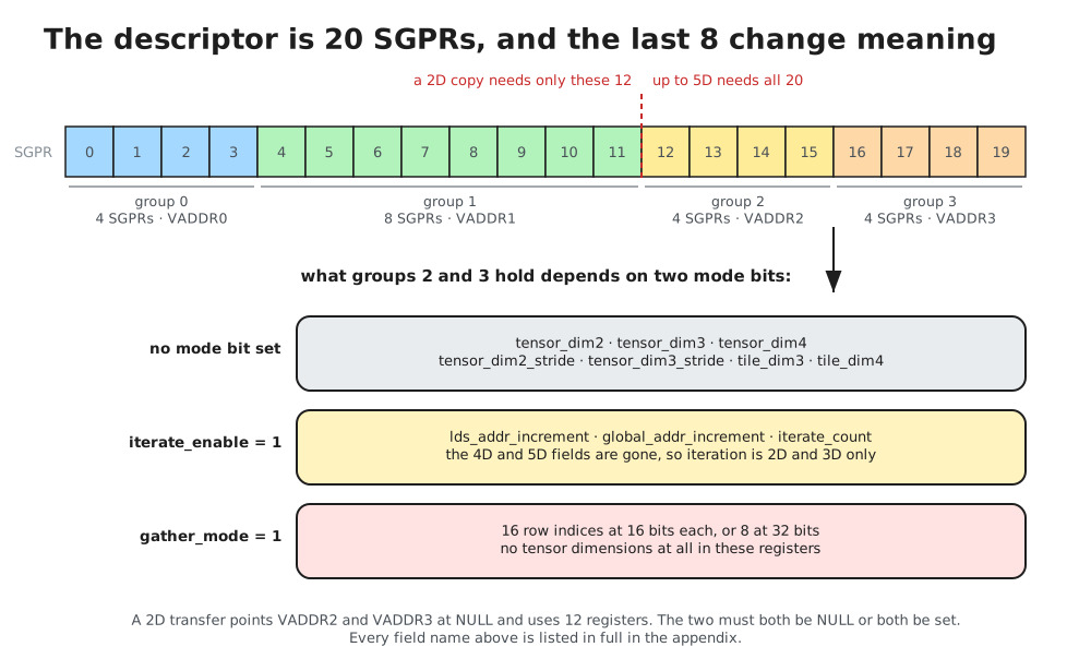
You don’t need the field names yet; the appendix lists them. What the picture is for is the shape. The descriptor is one contiguous block of registers, a 2D copy fills only the first twelve, and the last eight do not have a fixed meaning. Two mode bits reinterpret them: turn on iteration and the registers that held the fourth and fifth dimensions become address increments, turn on gather and they become a list of row numbers instead. That is why it behaves more like a tagged union than a plain struct, and why some combinations are mutually exclusive. Iteration borrows the registers a 4D or 5D copy would need, so you cannot have both.
The instruction returns immediately, so you need some way to ask whether the copy has finished. That’s a counter called TENSORcnt. It goes up by one when you issue a transfer and down by one when a transfer lands, and S_WAIT_TENSORCNT N blocks until at most N are still outstanding.
That N is the whole trick. Waiting for 0 means “wait for everything.” Waiting for 1 with two copies in flight means “wait for the older one, let the newer one keep running.” That’s what lets you build a pipeline instead of a stall.
One rule to remember: TENSORcnt only orders these transfers against each other. If an ordinary store has to land before a tensor load reads that memory, wait on the store’s own counter first.
Describing what to copy
This is the part that trips people up, so it’s worth going slowly.
The descriptor names two different things. The tensor is the whole array as it sits in memory. The tile is the smaller rectangle you actually want copied.
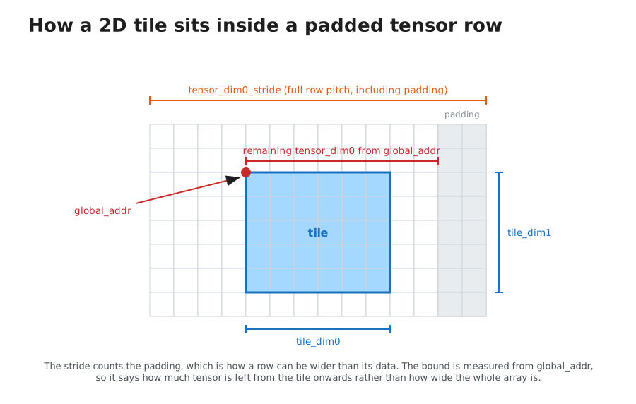
Two ideas in that picture do most of the work.
First, how much data there is and how far apart rows start are two separate numbers. The stride is the distance from one row’s start to the next, and it can be larger than the data in the row, which is how you describe a tile carved out of a bigger matrix or an array with gaps between its rows.
Second, the starting address points at the tile, not at the array. That catches everyone, and the manual calls it out explicitly:
global_addr — Global memory address of the start of the tile within the tensor (not the start of the tensor).
That second point has a consequence you can see in the picture. The engine is only ever told where the tile begins, so the bound it checks against is measured from there as well: it says how much tensor remains from the tile onwards, not how wide the whole array is. The next section is about what that gets you.
Walking a tile across a matrix is therefore cheap: two fields move, global_addr and the bound measured from it, while the tile extents and the strides stay as they are. You build the descriptor once outside the loop and adjust those two.
For a 2D array the engine computes each address like this:
address = global_addr + elementSize * (x + y * tensor_dim0_stride)Rows get read left to right and stacked into LDS back to back. However scattered the data was in memory, it arrives packed.
Running off the edge
Real matrices aren’t neat multiples of your tile size. The last tile in a row hangs off the end of the array, and normally you deal with that using a separate cleanup kernel or a slower guarded path.
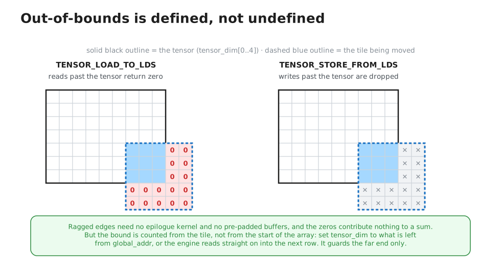
The engine handles it. Reads past the end of the array return zero, and writes past the end are thrown away, so the overhang costs you nothing and a full tile stored over a partial region can’t scribble on its neighbour.
One subtlety is worth spelling out, because it follows from something already said and is easy to skip past. Since global_addr points at the tile rather than at the array, the engine has no way of knowing where the array begins. The bound is therefore measured from the tile, and the manual says as much when it notes these fields can describe a sub-portion of a larger tensor. Concretely, with a 16-wide tile at column 56 of a 64-wide array and the width left at 64:
tile at column 56, tensor_dim0 = 64, tile_dim0 = 16
got:  56 57 58 59 60 61 62 63 | 64 65 66 67 68 69 70 71
Those last eight values are the next row rather than zeros: 64 elements were available from the tile onwards, so nothing was out of bounds. The field means “how much tensor is there from here”, which is what it has to mean given where global_addr points.
So the width travels with the tile. Set it to what is left from the current position and edge handling falls out:
ragged array, 40 real columns, 16-wide tiles
col  0, tensor_dim0 = 40:   0  1  2  3  4  5  6  7  8  9 10 11 12 13 14 15
col 16, tensor_dim0 = 24:  16 17 18 19 20 21 22 23 24 25 26 27 28 29 30 31
col 32, tensor_dim0 =  8:  32 33 34 35 36 37 38 39 | 0  0  0  0  0  0  0  0
That last row is the behaviour you want, and it costs one scalar subtract per step.
The other limit is that it only protects the far end, not a negative or underflowing address.
Padding, and why LDS has banks
LDS is split into 64 banks. Roughly: two threads reading different banks at the same time are free, two threads reading the same bank have to take turns.
That causes a classic problem. If a tile’s rows are packed tightly and the row length lines up badly with 64, every row starts in the same bank. Reading down a column then hits that one bank over and over, and the reads serialize.
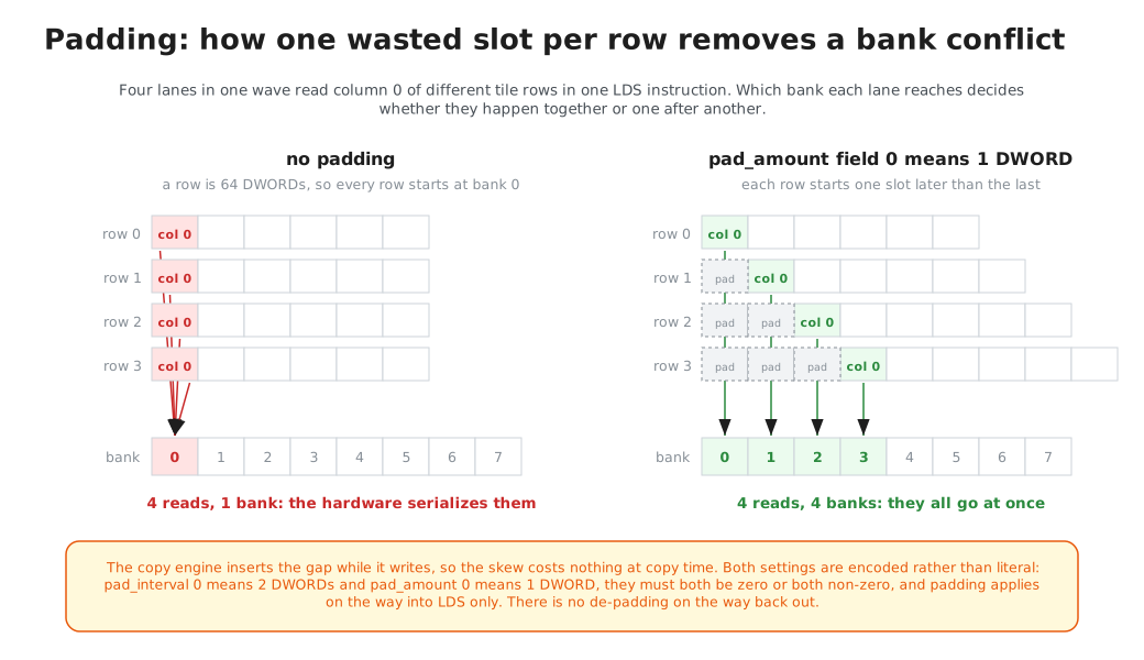
The fix is to waste a slot or two at the end of each row so the next one starts in a different bank. Reads down a column then spread across banks instead of piling into one, and they can be serviced together. Doing this by hand means extra address arithmetic on every store; the Tensor Data Mover will do it while it writes. Tell it how often to insert a gap and how big the gap should be, and it skips those slots as it goes.
Two warnings. The settings are encoded rather than literal, so writing 1 doesn’t get you 1, and they must both be zero or both be non-zero. And padding only works on the way in, since there’s no un-padding on the way back out.
Two extra tricks
Broadcast. In a large matrix multiply, many workgroups need the same slice of data, and reading it separately for each one wastes bandwidth.
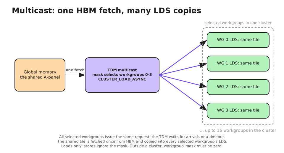
Set a 16-bit mask in the descriptor and one trip to memory delivers the tile into the LDS of up to 16 workgroups at once. They have to be part of the same cluster and they have to ask at roughly the same time; the hardware waits briefly for stragglers and then gives up on them.
Gather. Flip a mode bit and part of the descriptor stops holding dimensions and starts holding a list of row numbers.
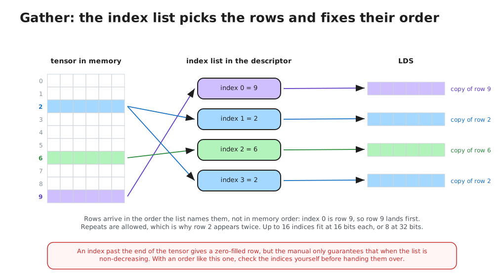
Up to 16 scattered rows get pulled together into LDS in one instruction, which is exactly the shape of an embedding lookup or a mixture-of-experts gather. Two things follow from the list being read in order. The rows arrive in the order you named them rather than in memory order, and an index may repeat, so the same row can be delivered to several LDS slots from one instruction.
One catch: the out-of-bounds protection from earlier is only guaranteed when the indices are in non-decreasing order. Since gather exists for cases where indices come from data, either sort them or check them yourself.
There’s a third mode, iteration, which replays one descriptor several times to pull out every Nth row. Useful, though it borrows registers from the higher dimensions, so it can’t be combined with a 4D or 5D copy.
The payoff
Here is what all of it is for.
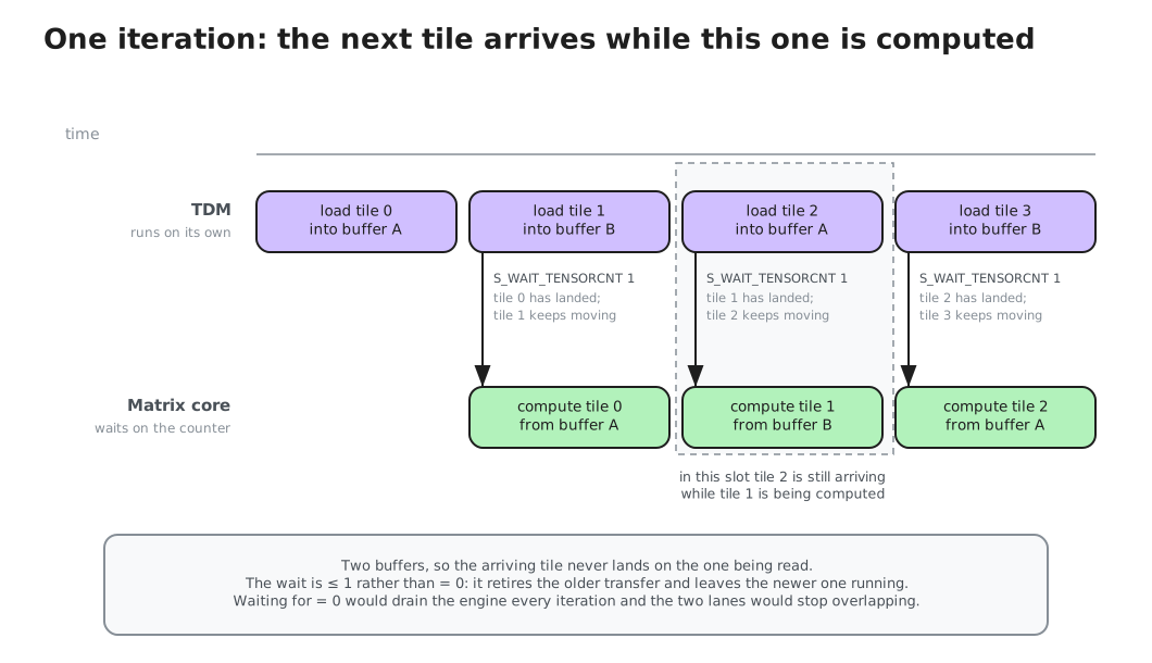
Start two copies before the loop. Inside the loop, wait for the older one, do the math on the tile that just arrived, bump the address, and fire off another copy. The engine stays a tile or two ahead of the matrix core.
loop:
  S_WAIT_TENSORCNT 1                   ; tile n has landed; n+1 still moving
  ...  compute on the tile that arrived ...
  s_add_u32   global_addr_lo, ...      ; advance the address, and shrink the
  ...                                  ; bound if this row is running out
  TENSOR_LOAD_TO_LDS  D#               ; start fetching tile n+2
  s_cbranch   loop
Per iteration the wave does one address update and issues one instruction. No per-thread address math, and no registers tied up holding data in transit. The copy is effectively free as long as the math takes longer than the fetch.
There’s one more piece for the common case where one wave fetches and many waves compute. The descriptor can ask the engine to signal an LDS barrier when the copy finishes. Consumers sleep on that barrier and get woken by hardware, so nobody spins on a flag.
Things to get right
A descriptor holds a lot of fields, and a few of them are worth committing to memory before you write one by hand.
- Two fields act as an off switch. tile_dim0 of zero makes the operation a no-op, and count of zero declares a null tensor, which also means no completion signal for waves waiting on the barrier.
- Several fields are encoded rather than literal, so the number you write is not the number you get. The padding pair is the one to watch.
- Faults are reported once for the whole operation rather than per transfer, which keeps the common path cheap and means isolating a bad field is a matter of narrowing down rather than reading an address off an error report.
- Group 0 carries fields the context save and restore machinery uses, marked must-be-zero. Zeroing them explicitly, rather than inheriting whatever the SGPRs held, is the difference between the operation you meant and a differently typed one.
- Driving this from inline assembly hides the LDS writes from the compiler, which is expected but easy to forget. My first correct descriptor appeared to return zeros because LLVM had folded away reads of a shared array that nothing visibly wrote, leaving no LDS loads in the generated code at all. A memory clobber does not cover it. Give the compiler a write it can see.
Worth knowing
Two things stand out after reading all this.
The out-of-bounds behaviour is more useful than it first looks. Zero on read, drop on write, checked against the real array bounds is exactly the right answer for ragged matrix edges, and it deletes a whole category of cleanup code that GEMM kernels otherwise carry.
And the counter matters as much as the engine does. A copy engine you had to fully drain before computing would only save you some instructions. Being able to say “wait until only one is still outstanding” is what turns it into a pipeline.
That is worth being concrete about, because it is easy to assume the DMA engine is the part that makes this fast. For a small tile it is not. One transfer on its own spends most of its time waiting on memory, and a hand-written copy loop does just as well. What buys you anything is the second transfer overlapping the first. Only once tiles get large does a single transfer keep memory busy by itself, at which point the counter stops mattering and the engine carries it. Which half is doing the work depends on how much data you move per instruction.
Appendix: the details this skipped
Everything above is the working mental model. This part is the reference material you need if you’re actually filling in a descriptor by hand, pulled from §10.11 of the manual and its neighbours.
Instruction encoding
Both tensor instructions use the VIMAGE encoding, with most of its fields either repurposed or forced to a constant. The ones that matter are the four VADDR slots, which hold SGPR addresses despite the name.
| Field | Meaning |
|---|---|
| VADDR0 | SGPR base of a 4-SGPR block: D# group 0 |
| VADDR1 | SGPR base of an 8-SGPR block: D# group 1 |
| VADDR2 | SGPR base of a 4-SGPR block: D# group 2, or NULL |
| VADDR3 | SGPR base of a 4-SGPR block: D# group 3, or NULL |
| VADDR4 | unused, set to NULL (0x7C) |
| SCOPE, TH, NV | memory scope, temporal hint, non-volatile |
That’s 4 + 8 = 12 SGPRs for a 2D copy and 20 for the full 5D form. VADDR2 and VADDR3 must both be NULL or both be set; you cannot supply group 2 without group 3. Passing NULL behaves as though you had pointed at zeroed SGPRs, and pointing both at the same block is legal if you want group 3 to duplicate group 2.
Tensor instructions may not appear in a clause. If your assembler groups memory instructions into clauses for issue efficiency, these have to sit outside them.
Address generation
Element size lives in data_size, log2-encoded in two bits: 0 is 1 byte, 1 is 2, 2 is 4, 3 is 8. The manual’s pseudocode decodes it as dataSize = (1 << D#.data_size), while the address formulas a page earlier write D#.data_size * as though the field held a byte count. Take the pseudocode as authoritative.
global_addr[2d] = D#.global_addr + dataSize * (x + y * D#.tensor_dim0_stride)

global_addr[3d] = D#.global_addr + dataSize * (x
                + y * D#.tensor_dim0_stride
                + z * D#.tensor_dim1_stride)

global_addr[4d] = D#.global_addr + dataSize * (x
                + y * D#.tensor_dim0_stride
                + z * D#.tensor_dim1_stride
                + zz * D#.tensor_dim2_stride)
Strides are cumulative, not per-dimension increments you multiply together. tensor_dim1_stride already contains whatever tensor_dim0_stride contributed, so if your instinct is to write z * dim0 * dim1, that multiplication isn’t happening in hardware. You supply the product.
The stride fields are 48 bits wide in elements, against a 57-bit global_addr, so neither will be your limit.
The manual’s own pseudocode for a 3D load, including the padding step:
Laddr = D#.lds_addr        // LDS write pointer
bytesStored = 0            // bytes written since last pad
dataSize = (1 << D#.data_size)

for Z = 0..D#.tile_dim2
  for Y = 0..D#.tile_dim1
    Maddr = D#.global_addr + dataSize * (y * tensor_dim0_stride
                                       + z * tensor_dim1_stride)
    for X = 0..D#.tile_dim0
        LDS[Laddr] = Memory[Maddr]      // dataSize sequential bytes
        Maddr += dataSize
        Laddr += dataSize
        bytesStored += dataSize
        if (D#.pad_enable && (bytesStored >> 3) >= (1 << D#.pad_interval))
            bytesStored = 0
            Laddr += D#.pad_amount
Two things to read out of it. There is no LDS-side stride field at all, so padding is the only way to get a non-contiguous destination layout. And dimension 0 is contiguous in both spaces, which is where your coalescing lives, so it wants to be the fast-varying dimension of the memory layout.
The pseudocode writes its loops as for X = 0..D#.tile_dim0, which is range notation rather than a literal bound: tile_dim0 is a plain count. Setting it to 8 moves exactly 8 elements and leaves the ninth LDS slot untouched.
Padding encodings
| Field | Bits | Encoding |
|---|---|---|
| pad_enable | 1 | off / on |
| pad_interval | 3 | power of two: 0 is 2 DWORDs, 1 is 4, up to 7 meaning 256 |
| pad_amount | 7 | offset by one: 0 is 1 DWORD, 1 is 2, up to 127 meaning 128 |
Constraints:
- pad_amount and pad_interval must both be zero or both be non-zero. Anything else “produce[s] unpredictable results,” which is neither zero padding nor an error. Since zero in each field means one and two DWORDs respectively, the setting you would naturally reach for as “smallest possible padding” is exactly the illegal one unless padding is switched off entirely.
- Padding is expressed in DWORDs while the rest of the descriptor works in data_size elements. For an FP8 tile, one unit of padding is four elements.
- tile_dim0 must be a multiple of 4 bytes for padding to work properly.
- Padding that would run past the workgroup’s LDS allocation is ignored rather than faulting, so an over-padded descriptor degrades into a differently laid out tile instead of an error you would notice.
The second use for padding, beyond bank conflicts, is transposes: the manual describes it as laying data out “in a pattern that may be easier for matrix transpose.” CDNA5 has DS_LOAD_TR16_B128 and friends (§11.2.4) to transpose on the way from LDS into VGPRs, and choosing a padding stride that makes those loads conflict-free costs nothing at copy time.
Completion and ordering
TENSORcnt is 6 bits, so up to 63 outstanding transfers per wave. The manual’s three ordering guarantees:
Tensor-Done is returned once per instruction, not per memory transfer. Tensor instructions complete in-order with other Tensor instructions from the same wave (both loads and stores stay in-order), but are unordered with instructions from other waves. Tensor instructions are unordered with respect to other types of memory instructions.
Completion is per-instruction, so the engine may split a tile into a hundred memory transactions and you still see exactly one decrement once all of them land. There is no partial completion to observe.
Same-wave transfers are FIFO, loads and stores together, which is stronger than ASYNCcnt gives you (there, loads and stores complete out of order relative to each other).
The third is the one to design around: TDM is unordered against every other memory type. A GLOBAL_STORE issued before a TENSOR_LOAD_TO_LDS from the same wave has no defined ordering against it.
One side effect worth knowing: §3.2.2.1 lets the hardware skip vector memory instructions when EXEC == 0, but only when LOADcnt, STOREcnt, ASYNCcnt and TENSORcnt are all zero. An outstanding transfer suppresses that optimization for the whole wave.
The barrier arrive
Set atomic_barrier_enable and supply atomic_barrier_address, a 64-bit-aligned LDS location stored as bits [18:3] with the low three implied.
A tensor op may optionally request that an LDS atomic occur after the tensor completes by setting D#.atomic_barrier_enable. When set, after a tensor operation completes it sends DS_ATOMIC_ASYNC_BARRIER_ARRIVE to signal its completion.
CDNA5’s LDS barriers (§11.2.2) are split-phase counting barriers with a pending count and a phase. When the count rolls under, hardware wakes sleeping waves in the workgroup and reloads the count. The arrive is also how the engine keeps successive descriptors from one wave ordered against each other at the LDS end.
Mode details
Multicast. workgroup_mask is 16 bits, one per workgroup-in-cluster. It applies to loads only; for TENSOR_STORE_FROM_LDS the field is ignored. It must be zero when the wave is not in a cluster, which the manual states twice, suggesting a real correctness hazard rather than a benign no-op. The underlying mechanism is a rendezvous with a timeout: every masked workgroup is expected to make the same request, and data returns once they all have or the timeout fires, with late arrivals getting their own separate broadcast. early_timeout tells the GL1 to return data as soon as GL2 supplies it, to whoever has shown up. Multicast loads force-miss the WGP$ regardless of scope and temporal hints.
Iteration. The extra fields are global_addr_increment and lds_addr_increment, both in elements, plus iterate_count where 0 means iterate once and 255 means 256 times. 2D and 3D only. Turning it on overloads three group-2 fields: tensor_dim3 becomes lds_addr_increment, tensor_dim2_stride becomes global_addr_increment, and tile_dim3 becomes iterate_count. Those are exactly the fields a 4D or 5D tensor needs, which is why the two can’t be combined. iterate_enable is ignored outright when gather mode is on.
Gather. Groups 2 and 3 become a list of row indices: 16 at 16 bits each, or 8 at 32 bits. tile_dim1 is redefined as how many indices are valid, and each row comes back as height 1 by width tile_dim0. tile_dim2 and tile_dim1_stride are ignored. Bounds checking against tensor_dim1 still happens, so an out-of-range index gives a zero-filled row rather than a fault. The same index list applied to a store gives you scatter. 2D only. And the caveat from the body, in the manual’s own words:
Random index selection is supported; indices are not required to be strictly increasing and may repeat. However, correct handling of out-of-bounds (OOB) accesses only occurs when each index is greater than or equal to the previous index.
Faults and edge cases
MEMVIOL is reported if a tile address falls outside the wave’s LDS allocation (and only when LDS_CONFIG.ADDR_OUT_OF_RANGE_REPORTING == 1), or if the global address lands outside the global aperture, meaning scratch, LDS or the hole.
MEMVIOL does not cause the TDM to abort — it continues processing the entire descriptor and return MEMVIOL to the wave when it’s done. Memviol and XNACK-error is reported once for the entire TDM operation, not per data transfer.
XNACK-retry is absorbed by the engine, so page faults on the DMA path resolve without the wave’s involvement. XNACK-error can still surface, for a write to a read-only page for instance, and it is explicitly imprecise: “the wave cannot rewind the PC to the faulting instructions.”
Group 0 carries five fields (count, is_restore, is_store, nv and User_null) all marked “User: must set to zero.” They exist because the same descriptor format is reused by the context save and restore machinery, and is_restore = 1 lets the restore path override the instruction’s own load/store direction. Leaving stale values there does not give you a bad tile, it gives you a differently typed operation. The type field in bits [127:126] must be 2 (“image”), so a descriptor built from zeroed registers isn’t valid at all.
Two fields turn the operation into a no-op: tile_dim0 == 0 makes the tensor a NOP, and count == 0 means “NULL tensor, no memory is copied, no atomic_barrier sent.” The second is worse, since it also never signals the barrier your consumers are asleep on.
tile_dim1 through tile_dim4 use 0 for “dimension unused” and 1..Max for a real extent, so there’s no way to express a legitimately empty higher dimension.
In-flight DMA is part of saved wave state. There’s a message, RTN_SAVE_WAVE_HAS_TDM, to “inform the CWSR machine this wave needs to be saved and has outstanding TDM ops,” and the group-0 count field carries separate user and context-restore meanings. VMID or pipeline kill stops all descriptors for the affected waves, and killed ops still return done so TENSORcnt drains, so a wave being torn down won’t deadlock on a wait.
References. Quotations and field details come from AMD’s “CDNA5” Instruction Set Architecture Reference Guide, mainly §10.11 (Tensor Data Mover Instructions), with supporting material from §2.3 (Workgroup Clusters), §5.7 (Data Dependency Resolution), §10.7 (Multicast Load), §10.8 (Asynchronous Memory Load and Store) and §11.1–11.2 (Local Data Share Operations).